Instructions for locking TSOP
To
Lock the TSOP, Connect the 2 wires that are exiting the back of the chip with the jumper.
When switching from locked to unlocked, make sure you unplug
your receiver
*If
you get an error message saying "There is a Serious Problem Detected" click here.
Hint: If you are having trouble getting your
soldering connections to stay, try applying super glue over the conectins after you have
soldered them, this usually will do the trick! |
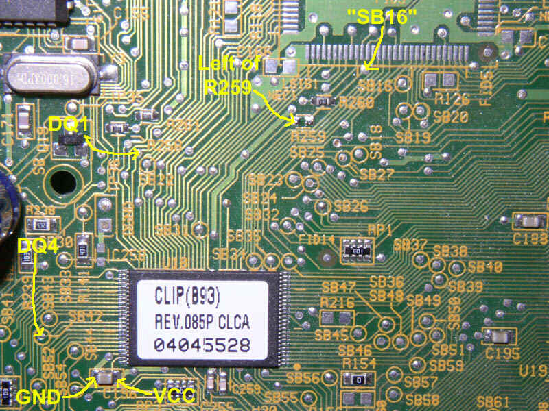
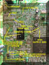
For x700, x800, x900
Receivers w/ R259:
Pin 1 (Orange) goes to WE TSOP
Side (Left of R259)
Pin 5 (Brown) goes to WE Supply Side (Upper Left of SB16)
Pin 7 (White/Brown Stripe) is grounded (left of C196)
Pin 8 (White/Blue stripe) goes to DQ4 (SB42)
Pin 9 (Green) goes to DQ1 (Upper Left of SB22)
Pin 14 (Blue) goes to VCC (right of C196)
|
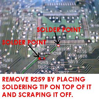
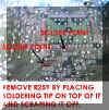 To remove R259 |
 x700, x800, x900 Board w/R259 |
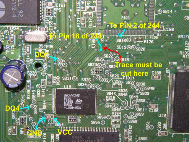
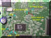
For x700,
x800, x900 Receivers without R259:
Pin 1 (Orange) goes to WE TSOP
Side (To
Pin 18 of 244 in picture)
Pin 5 (Brown) goes to WE Supply Side (To
pin 2 of 244 in picture)
Pin 7 (White/Brown Stripe) is grounded (left of C196)
Pin 8 (White/Blue stripe) goes to DQ4 (SB42)
Pin 9 (Green) goes to DQ1 (Upper Left of SB22)
Pin 14 (Blue) goes to VCC (right of C196) |
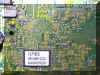
x700, x800, x900 Board W/out R259
|
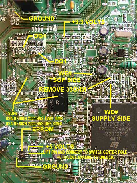
For 301.013
Pin 1 (Orange) goes to WE# TSOP
Side
Pin 5 (Brown) goes to WE# Supply Side
Pin 7 (White/Brown Stripe) goes to Ground
Pin 8 (White/Blue stripe) goes to DQ4
Pin 9 (Green) goes to DQ1
Pin 14 (Blue) goes to VCC +3.3 Volts
|
| Click here to download 301.010 instructions Pin 1 (Orange) goes to WE# TSOP
Side at R259
Pin 5 (Brown) goes to WE# Supply Side at SB16
Pin 7 (White/Brown Stripe) goes to Ground at R254
Pin 8 (White/Blue stripe) goes to DQ4 at R281
Pin 9 (Green) goes to DQ1 at R263
Pin 14 (Blue) goes to VCC +3.3 Volts at R282
|
Click Here for Eeprom
Lock Instructions |